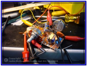
A week or so ago, I posted a note about the Gnat 1 single transistor QRP transceiver. I was excited about building this little project. I gathered up the parts and warmed up the soldering iron.
The project went together easily. After all, there are only about a dozen parts or so, what could go wrong? Oh, what a loaded question that was.
I decided to construct the 80 Meter model. I live about 20 miles out of Helena, MT, and if I was successful in getting this little rig working, I wanted to see if a fellow Ham in Helena could detect my signal. After completion, I attached the power, and antenna. I hooked up the oscilloscope and frequency meter, and powered the rig up.
I was immediately gratified with a signal when I shorted the “key” line. It looked like I was getting out between 200 and 400 milliwatts, depending on the power supply voltage. This is where the fun ended.
I was never able to detect any sort of audio out of the little rig. I followed the tuneup procedure in the instructions to the tee. The instructions were easy to follow and the results were exactly as written, but through all of the test procedures, I was “NEVER” able to detect any audio. After several days, I think I am done with it. Unless something else pops into my mind, I will cut my losses on this one and continue on to the next project that is begging for my attention.

I ran across the Gnat yesterday Aug. 5th 2011. It was interesting because
back in 1996 I thought about doing such a rig but thought the regeneration
would be too hard to adjust and the bandwidth too narrow due to the crystal.
In this rig, the designer runs the crystal with a high resistance in series due
to the input impedance of the transistor. If it works as an oscillator then you
should be able to adjust the regeneration to hear a hiss and signals. One
problem I saw was the schematic seemed unclear as to which winding was 8
ohms. Likely the 0.1 uF capacitor tunes the 1000 ohm winding to resonance
at an audio frequency. If you have a transistor with more or less current gain
than what the designer used, you might have a problem. There is a large
variation from lot to lot in transistors. Hopefully you double checked your
wiring, and it is easy to accidently put in a resistor off by a power of 10. You
might play around with values in the bias resistor voltage divider; or try a Pot.
there instead of resistors. Make sure that the 500 ohm Pot. is a good one and
for sure 500 ohms. And maybe you accidently put in the wrong transformer or
put it in backwards. And, I would think that the Headphones used could be
very critical; you might try connecting an audio amp. instead of headphones
or at least a unity gain connected Op. Amp. and electrolytic coupling capacitor
to buffer to the headphones. The schematic says Speaker, so I assume that is the
8 ohm winding on the transformer. The 8 ohm winding should only measure an ohm
or 2 on an ohmmeter. One way or the other, you ought to eventually get it going.
And, by the way, you might try a different band because the crystal characteristics
change so much from band to band. One other problem: the oscilation frequency
needs to change several hundred hertz between transmit and receive in order to
hear a station coming back to you on frequency. If the freq. shift between Tx and
Rx is too small, many stations would come back near zero beat and you will not
hear them. And, I would expect that the regeneration might have to be readjusted
everytime After you Key the transmitter? The tramsmit signal might knock it out of
adjustment so the QSK ends up not working properly. I would expect all sorts of
possible problems with a regenerative transceiver, especially if it is crystal controlled.
And, only a few picofarads of stray capacitance at the transistor input could totally
change the impedance that the crystal works into. Perhaps you have built the circuit
on copperclad board and greatly increased the stray capacitance at the base of the
transistor? Raise the Node of the crystal, transistor base, and bias resistor divider
off the circuit board.
Dan
Hi Dan,
I just recently ran across the Gnat article and getting ready to give it a try. Their is another circuit on the web I also found by the Four Square QRP group.
Did you get your model running?
I am getting ready to give it a try also. The shift between Rx and Tx seem like it could be a problem.
Stan AK0B
w9ifz at yahoo.com