Repairing My Icom IC-706MKIIG Final Amp Board

Final amp board with old finals removed, and ready for board modifications.
IC-706MKIIG amplifier board with new final transistors mounted in modified circuit board.

A few YEARS ago, I noticed that my Icom IC-706MKIIG Amateur Radio Transceiver was very hot.  The problem was, it was NOT turned on!  I immediately unplugged it from its 12V powers supply, and pondered it for a long time.  Apparently, the final amplifier transistors in the IC-706MKIIG are not wired through the power switch, but they get their power directly from the 12VDC line coming into the radio.  If all is working well, and there is no drive to the transistors, there is no current drawn.  One of mine, was drawing current, and a lot of it, all the time.  Ten Amps of current, all the time.

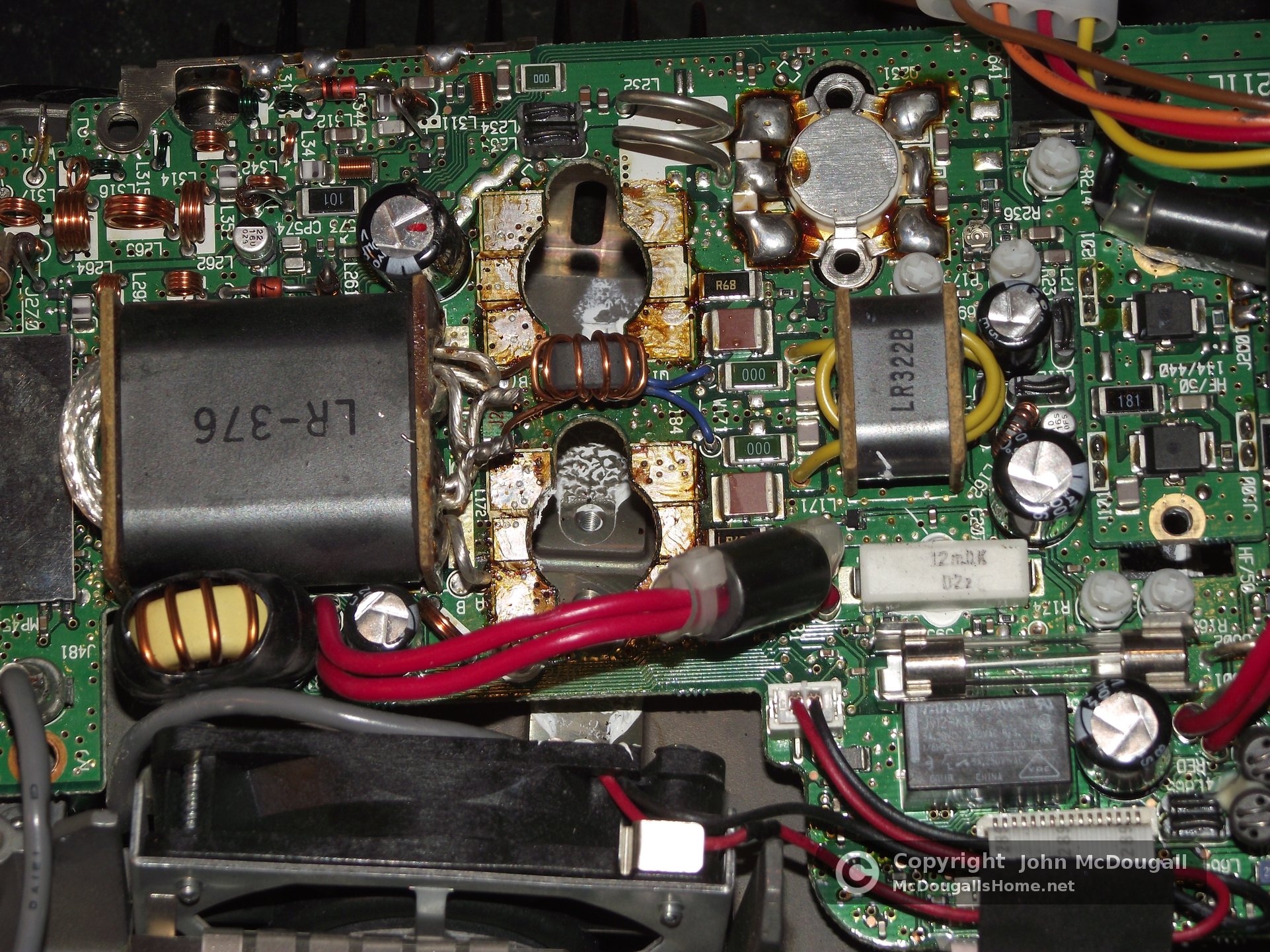
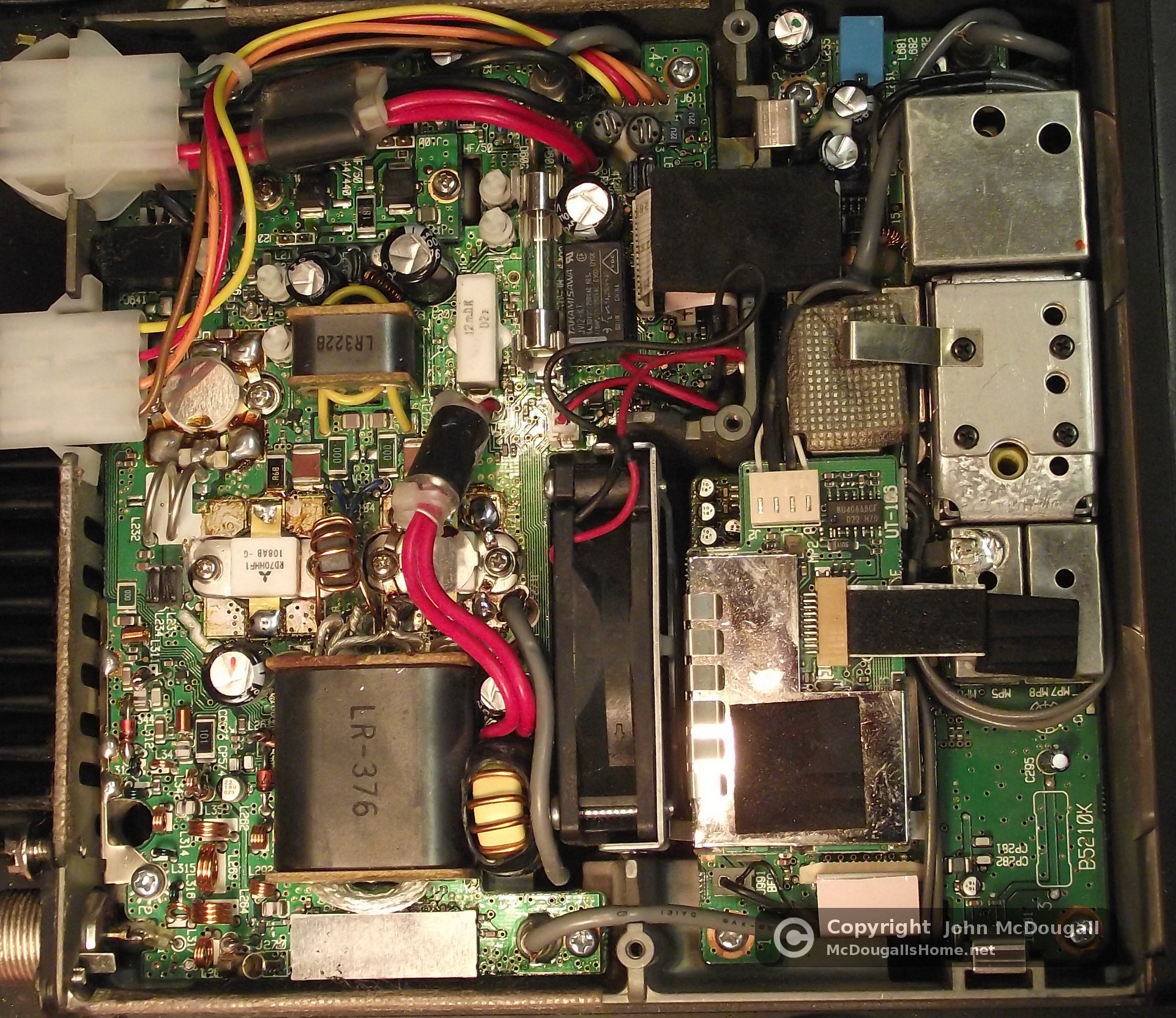
My radio sat for a few years, with me occasionally looking at it and wondering what to do.  Finally, in late 2012 or early 2013, I contacted a repairman about my radio.  The ball was moving to my court, because #1: the repairman was too busy to take additional jobs, and #2: the repairman informed me that my radio was of an “old” design.  It had SRF-J7044 Mosfet transistors for the HF finals.  They were no longer being made, and they are extremely rare to find.  An alternative was to “replace” the final amplifier board at the cost of over $400.  No thank you!

I did a lot of searching around and found Jose Gavila’s (EB5AGV) web site. He replaced the transistors in one of these older Icom radios with newer transistors, and he documented it very thoroughly.  Being a hardware kind of a guy, I decided I could do the repair following his steps.  And here are the results.  I videoed the process for your viewing pleasure.  If you have an older IC-706MKIIG with the same problem, you CAN repair it.

As a side note about the Icom IC-706MKIIG:  Apparently, damage can be done to the final transistors while the rig is off when the installation is in a vehicle.  I did have mine in a vehicle at one time.  Constant starts of the vehicle, and heavy loads and fluctuations at the battery, enter the radio, and are applied to the finals because of the previously mentioned problem with them not being switched.  If my radio again ends up in my vehicle, I will have it switched, so I can make sure no power is applied to it while I start or stop the engine.

Most of this information was found at EB5AGV’s web site at:
http://jvgavila.com/ic706.htm

Thank you a thousand times for the nice details that Jose, EB5AGV provided in doing this mod.

–John, K7JM

embedded by Embedded Video

YouTube Direkt


Ham Shack Windfall

Our local radio club, Capital City Amateur Radio Club, (http://w7tck.org) was donated a bunch of equipment. We decided to have a silent auction for it for the club members. The idea was to allow members to obtain some equipment inexpensively rather than try to make a bunch of money off of it. Here is my windfall.  WOW! What Fun!

Click to see a slide show of my new equipment.

Click a picture to see a larger view, or click HERE for a slide show of my new “Junque”.

My favorite acquisition was this beautiful Heathkit SB-230 Amplifier.  When I built my shack several years ago, I plumbed into it 220 Volts for that day that I may have an amp.  It is about 1 KW input (probably about 600 Watts output), but that is very sufficient for me, since I operate in the QRP range much of the time.  This will be fun too though!  Look HERE to see my Ham Shack equipment; and you will see that I like Heath gear.

Heathkit SB-230

The photo below shows an old Heathkit Impedance Bridge.  At first, I was hoping it would be an instrument I could use to measure impedance of RF circuits, but it is usable at audio frequencies.  Non the less, it is a beautiful instrument with a wooden case and will sit up on my shelf with my other vintage items.

Heathkit Impedance Bridge IB-1B

The photo below is of a James Millen model 90662-A Grid-Dip Meter.  It is in perfect shape and is a very beautiful piece of test equipment.  I have a much older Heath grid-dip meter that I have been using that I will be glad to put up on the antique shelf, and put this beauty to use.  It is really a nice piece of test gear and a welcomed addition to the Ham Shack.

James Millen Grid Dip Meter 90662-A

The picture below is of a Heathkit Tube Tester model IT-17.  I have wanted a tube tester for many years, and passed up an opportunity to acquire one a couple of years ago and have been beating my self up over it ever since.  Since I have vacuum tube equipment, this will come in handy at that time in the future when it will be needed.  Tube testers are becoming increasingly rare and I am glad to add this one to my test equipment collection.

Heathkit IT-17 Tube Tester

The picture here, is of a Step Attenuator.  I have been thinking about either building, or purchasing one of these for a while now.  Of all the pieces of test gear I purchased in this sale, this is probably the most practical.  I am eager to put it to use while I learn and build transmitter and receiver circuits.  This is going to be a good piece of gear to have.

Step Attenuator

The following picture is a Wilcom Reference Level Test Set model T 105B.  I believe it was used with phone systems.  I purchased this gem for the case.  It is a very nice case that has nice rubber feet, handles on the instrument face, buckles to keep the lid closed, and a rubber seal to help keep the elements out.  It would make a very nice case for a piece of portable radio equipment that might be made some day for it.  It looks like it will be a good source of some nice parts also.

Wilcom Test Set T 105B

Here is another piece of Heathkit gear.  It is a model IM-5228 VTVM (Vacuum Tube Volt Meter).  I really purchasedit for the meter movement and for parts.  I might, however, keep it together as I do not have a good analog meter.  I fired it up and it works, so I might keep it around for those times an analog meter will do better than a digital one.  It will make a nice addition to my test gear collection.

Heathkit IM-5228 VTVM

There was a few odds and ends that the club was trying to just get rid of.  I just couldn’t let this one go to the dump, so I acquired it.   I’m sure I will be able to use some parts of some sort from this box of goodies.

Junk Box

ARRLWeb: ARRL NEWS: Classic Exchange — A Vintage Radio Contest

The following is portion of a news entry from the ARRL. Click the link and read the whole post;  and if you have some vintage gear, fire it up and get ready for this fun sounding contest.  I am hoping that I will be able to participate in the fun.  Will you join me?
John – K7JM

Click the picture of my Vintage Heathkit gear and take a tour of my Ham Radio Shack.

Classic Exchange — A Vintage Radio Contest

By Mario Dianora, N2AK
dianoramd@verizon.net

ARRL – January 09, 2009


Warm-up those filaments for the Classic Exchange contest, January 25/26 and February 15/16.


Do you have any old equipment from the bygone days of radio? Are you a homebrewer who likes to make nifty low power (QRP) radios or replicas of old rigs? Well the good news is that you can put those pieces on the air in an operating event that will make you feel like you are in another era. That event is called Classic Exchange (CX) and it is held twice a year. The purpose of CX as described in their newsletter is to “Encourage restoration, operation and enjoyment of older commercial and homebrew ham gear.” Some years ago, I heard stations on 40 meter CW calling “CQ CX.” After some research, I discovered that this was a contest for vintage and homebrew gear. It sounded like a great way to get some use from the old rigs I had in my basement. Since then, I have rediscovered the magic of radio and await the next CX event for more of it.

via ARRLWeb: ARRL NEWS: Classic Exchange — A Vintage Radio Contest.

Capturing The Elusive Leap Second

My Leap Second Capture Setup
My Leap Second Capture Setup. Click the picture to see a larger view.

A “Leap Second” was added to our clocks at 12:59:60 on Dec. 31, 2008 (12:59:60 is not a typo).  Leap Seconds are added or subtracted every so many years, to keep our clocks in sync with the actual orbit of Earth around the sun.  There are several different methods to capture the leap second, and I took the opportunity yesterday to see if I could do the same without fancy or expensive equipment.

HERE is a good web site about the “Leap Second”.

And, HERE is a page about how to watch a “Leap Second”.

This is how I did it.  I tuned into WWV on my Ham Radio receiver, and set up a camera to record the time on my GPS.  After looking at the Leap Second web site, I should also have connected my computer to my GPS to capture the NMEA output from it.  Click on the picture to the left to see my setup. View the video below, and you will see that 12:59:59 lasted for two seconds on the GPS.

John – K7JM

The Lonesome Tower

I could put this old tower to good use.

I spent a couple of days on the roads in Eastern Montana. While out there, I spotted this old abandoned house with a tower attached to it.  It is just begging to be put to good use once again.  And, I would be willing to be the one to put it to good use.  I’m not sure how I could find the owner, or how I would get it across the state; but it is something to keep my mind occupied for awhile anyway.  Click on the picture to see a larger view.  Then, click on the little green arrow at the bottom of the picture to see the picture at full zoom.  John