W7MRI’s Anderson Powerpole
Power Hub
This information is provided by K7JM at http://radio.McDougallsHome.net
Download PDF of this page

![]()
Don, W7MRI, made up a nice small circuit board that holds 7 pairs of Anderson Powerpole connectors to distribute 12 volts to equipment that has matching Powerpole connectors. These nice little connectors are becoming a standard for low voltage DC devices. Here is a photo essay of the assembly of one of these little kits. At the time of this writing, Don sells a pack of 7 pairs of Powerpole connectors and the circuit board for $15. Other configurations are also possible with this little board, but here is the most common. Contact Don, W7MRI at ‘w7mri<at>mt.net’. Don also regularly attends the Capital City Amateur Radio Club‘s monthly meetings, and very often shows up at Hardee’s in Helena on Saturday Mornings from about 10:00 am to 11:00 am.
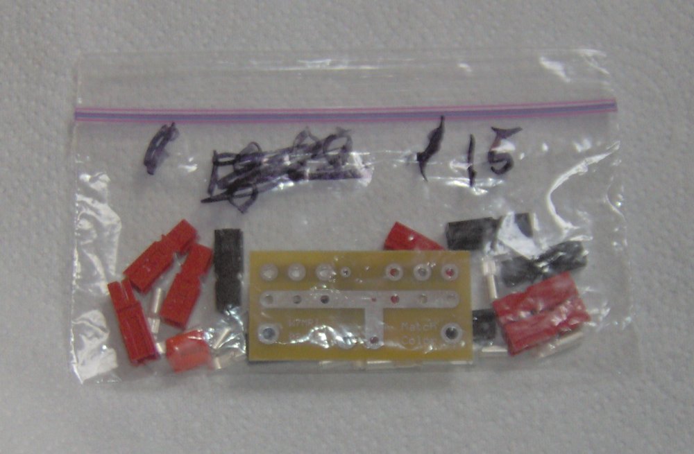 |
This is the package that Don sells for $15. It contains the small circuit board, seven pairs of Anderson Powerpole shells and fourteen silver plated contacts and one capacitor. |
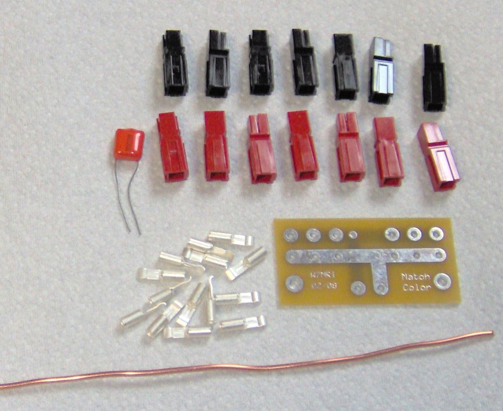 |
Here are the parts all laid out. You will need to supply about two feet of number 12 house wire, stripped. |
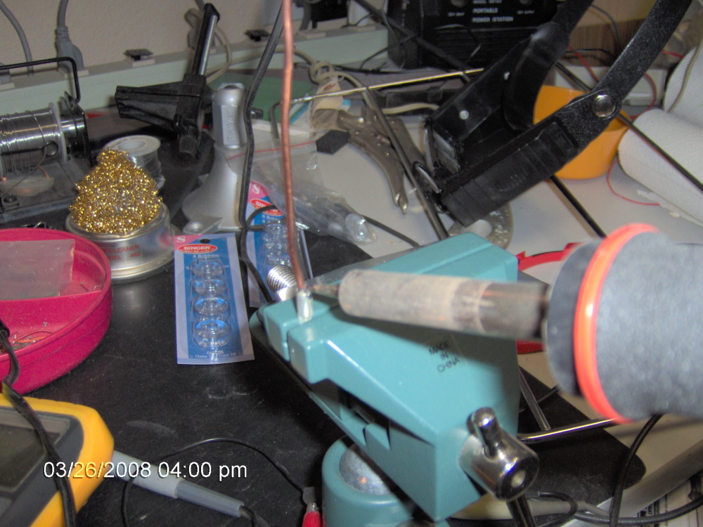 |
Here I am soldering the #12 wire into a contact. I carefully held the contact in a vise, then set the wire into the connector and soldered it. I did not crimp the connector. Be careful not to get solder on the contact part of the connector. I left the wire long while soldering and trimmed later. |
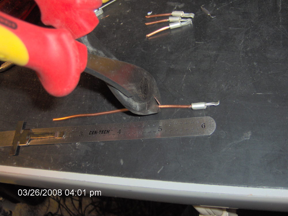 |
I cut the wire to the length of about one inch. That is over 1 1/4 inches counting the whole length of the contact. Don’t cut them too short or you will have trouble later. I cut one pretty short, but it was still long enough. I soldered and trimmed one at a time. |
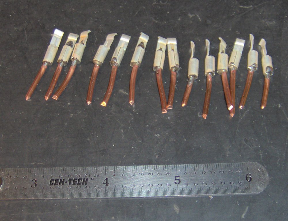 |
Here are all the trimmed pieces. As you can see, I got one nearly too short. |
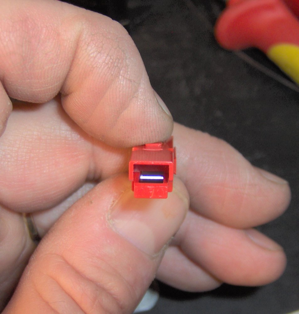 |
Take a connector shell and position it with the small metal piece toward the bottom. We will insert the contact into the shell. |
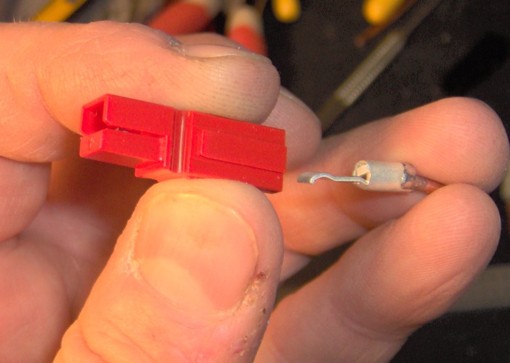 |
With the shell in the same position as the previous picture, slide a contact into the shell as shown. |
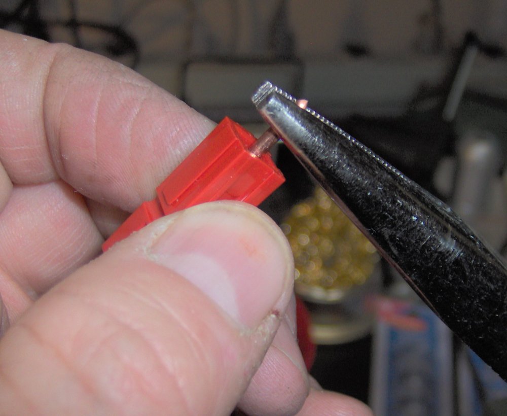 |
Use some needle nose pliers and firmly push the contact into the connector shell. The contact should very distinctly snap into place with a “click”. If the wire is crooked, bend it slightly to make is centered and straight. |
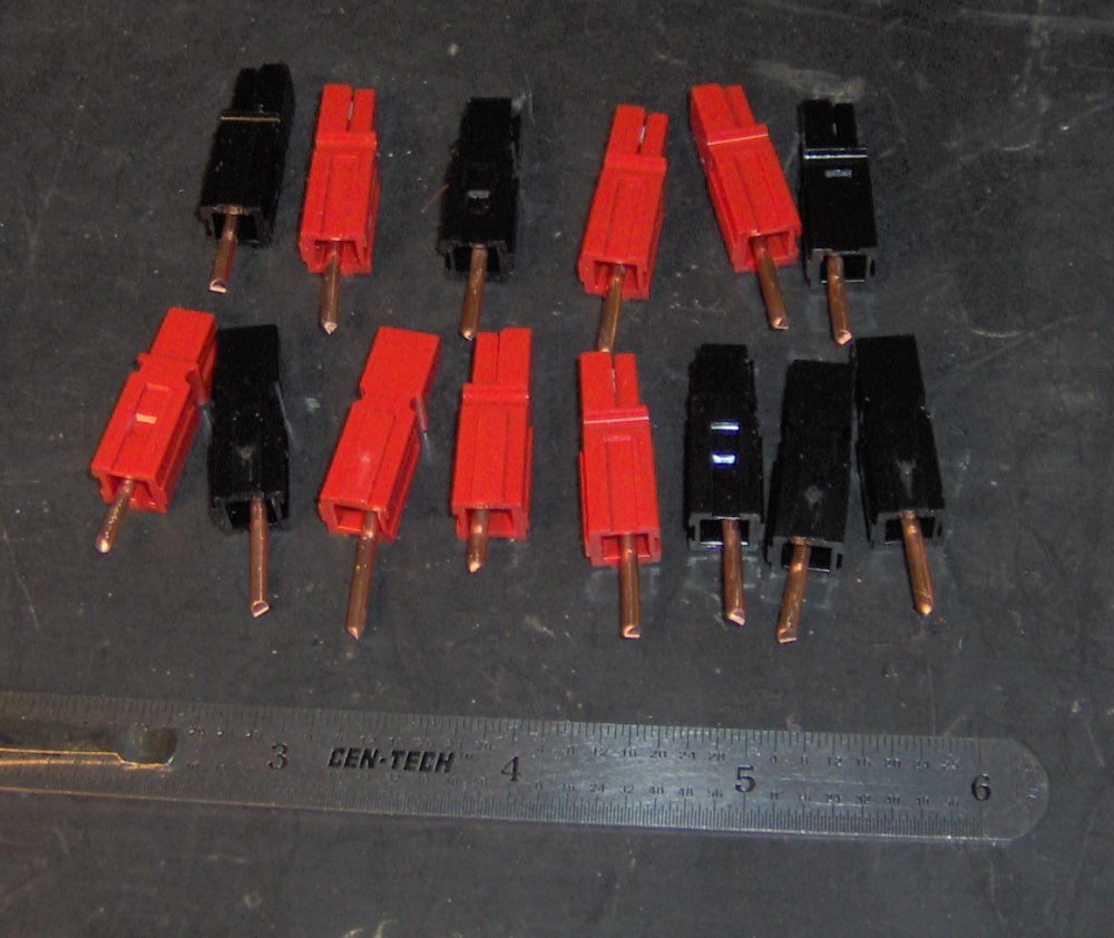 |
Here are all connector shells with the contacts installed. Notice the one I cut nearly too short. |
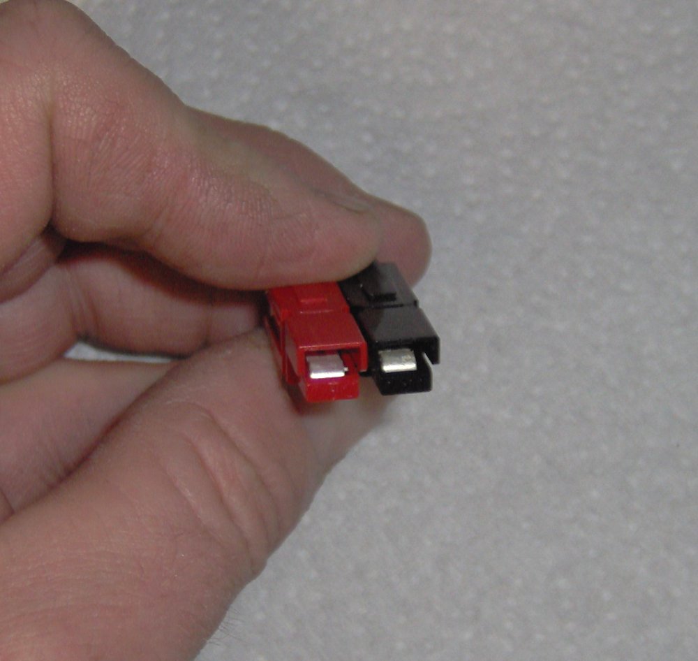 |
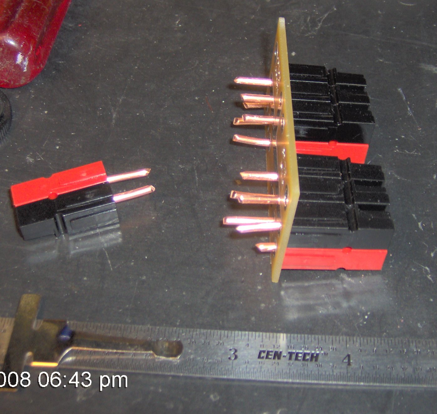
In this step, I connected pairs of connectors together. Anderson Powerpoles will connect together in several ways so it is important that you do it correctly. There are two standards of how they are connected. As shown in the picture, the red is on the left, with the contacts on the bottom. This is the way most commercial connectors are assembled. Many local hams assemble the connectors with the black on the left instead of the red because this was supposed to be the standard, then manufactures of other powerpole products reversed the order. I changed all of mine to match the commercial products. Be aware that when you plug a device into these, that red MUST match up with red, and black with black; because if they are reversed, the connectors will still go together with the wrong polarity. |
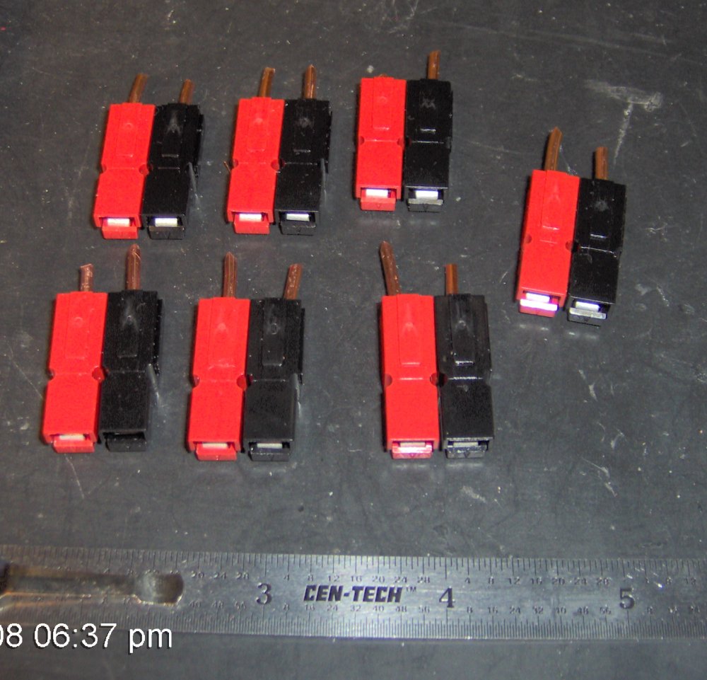 |
This picture shows all connectors paired up. All with red on the left when the metal contacts are on the bottom. |
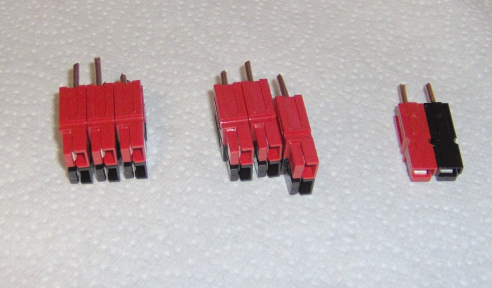 |
Now, assemble three pairs together as shown, with all red on one side and all black on the other. Make two assemblies of three, with one pair left by itself. |
 |
Take the two sets of 3 connectors and carefully push them through the circuit board making sure all black connectors are on one circuit trace, and all of the red ones are on a separate circuit trace. Take care that each set of three are assembled the same way. If necessary, use needle nose pliers and guide the #12 wires through the hole. Bend them slightly if necessary. |
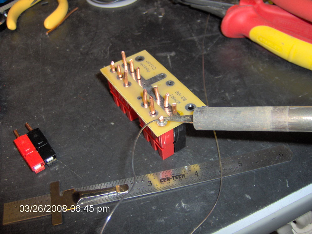 |
Solder each wire coming from the connectors. Push the connectors firmly against the circuit board before soldering. |
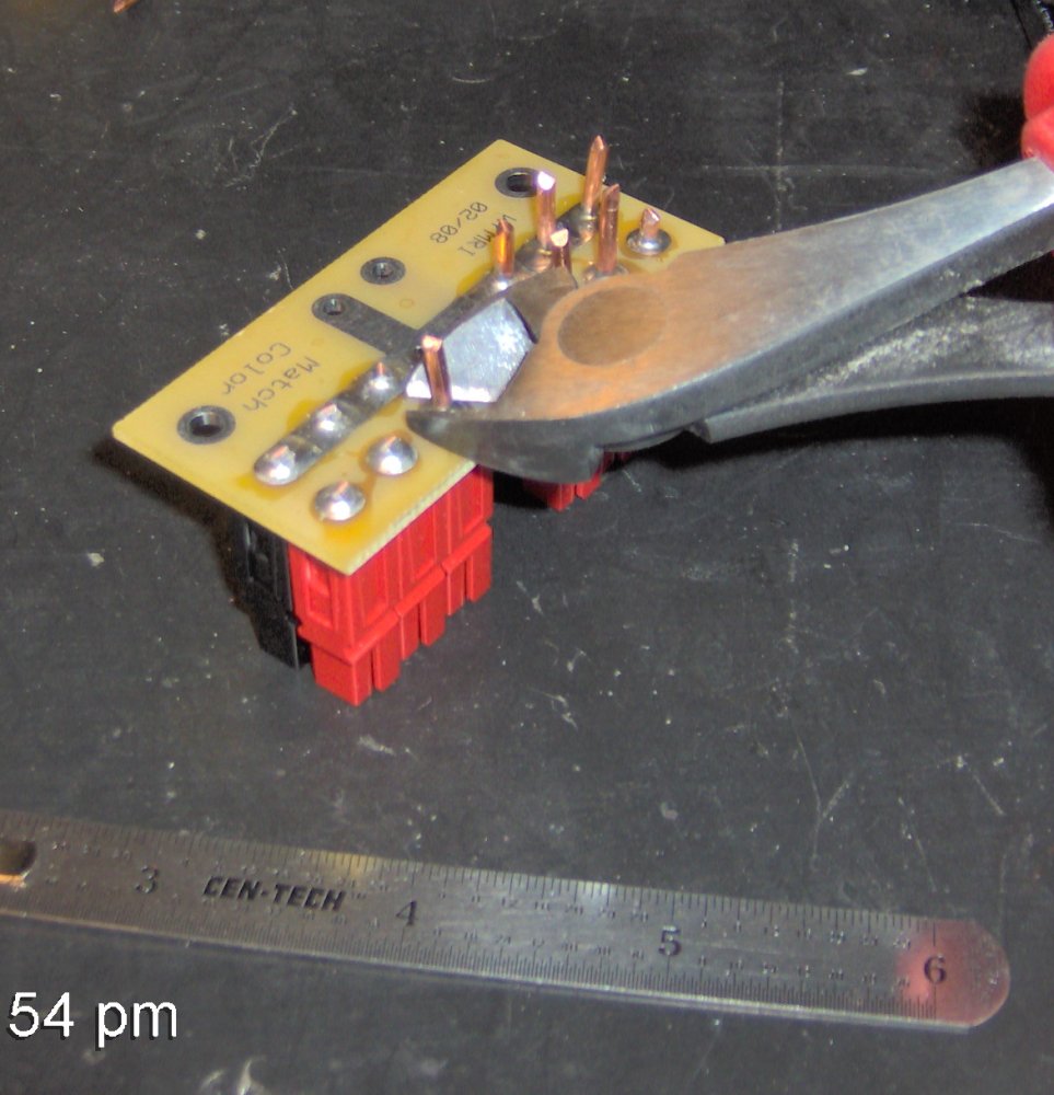 |
Cut off excess lead length. Be very careful as the wire tend to fly when they are cut and can be a hazard to you eyes. |
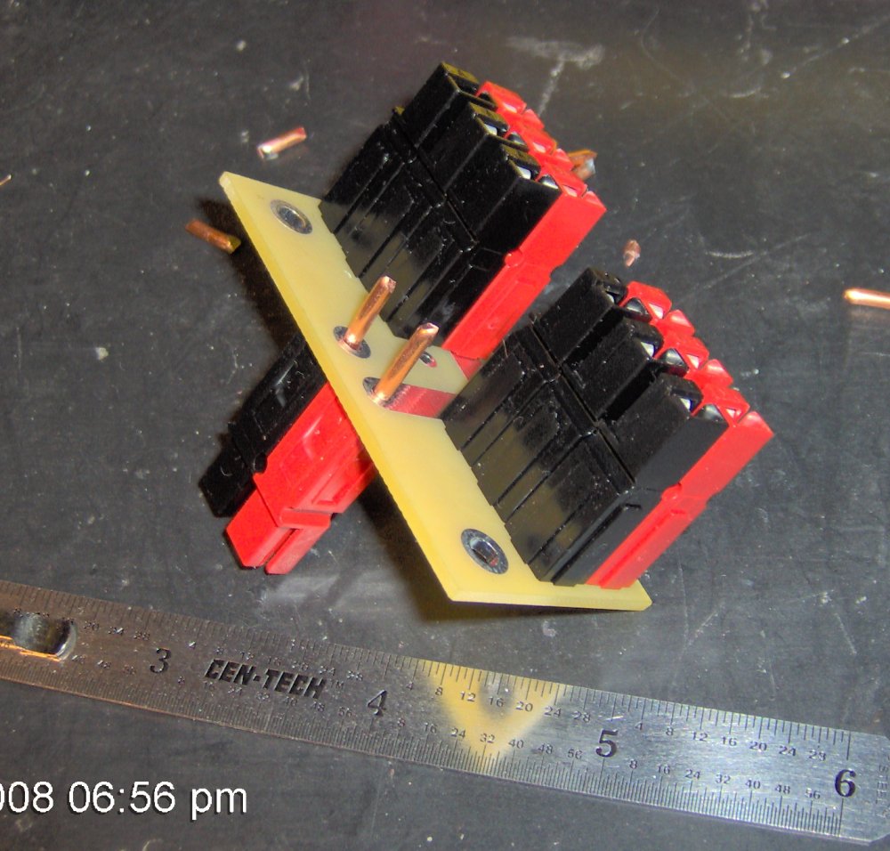 |
Now, on the opposite side of the circuit board, place the final connector. Take care to be sure that the black side is attached to the traces with all of the other black connectors, and the red shell is on the same circuit board trace as all the other red shells. Make sure it is set firmly against the circuit board, solder the leads, and cut excess lengths off. |
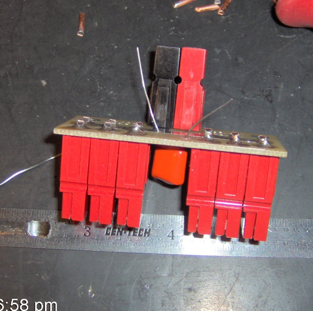 |
Locate the orange capacitor. Place the leads through the two small holes remaining in the circuit board. Push the capacitor down to the circuit board and slightly bend the leads outward to hold the capacitor in place. Solder the leads, and clip the excess lengths off. This completes the assembly of the power hub. |
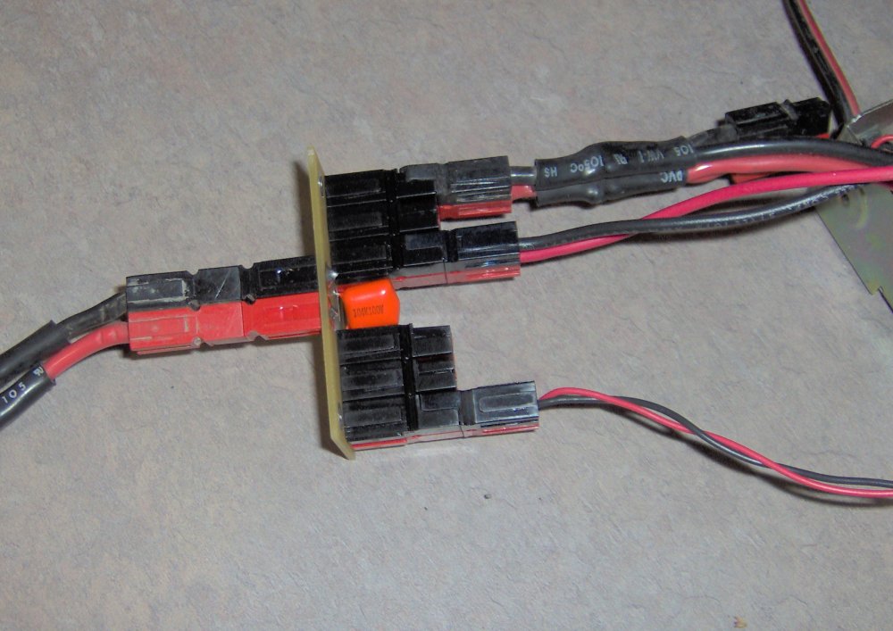 |
This photo illustrates the actual use of Don’s Power Hub. There are two mounting holes in the hub to attach it. It is suggested that the power hub be placed in a proper insulated container. The DC power from a power source is generally applied to the single connector on the one side of the circuit board and power is distributed to your devices through the six connectors on the other side of the board.
Different arrangements can be made with this little board. You can add six more connector pairs on the opposite side of the board, or you can have your power source connector on the same side as all the other connectors. This is a very versatile little project that will make your life easier without breaking the bank. Thanks Don, for creating this little project. |
Copyright K7JM John McDougall 2008
radio.McDougallsHome.net